
Install the Adafruit Unified Sensor library.Install the latest open source Arduino IDE.Make sure a LoRa gateway is in your area and the LoRa node can send messages to that gateway.Stack two female pin headers (2x) and place them on the breadboard with the LoRa module on top. Wiring HopeRF RFM95 LoRa transceiver module and Arduino Pro Mini. The Arduino Pro Mini is the Master and the HopeRF RFM95 LoRa transceiver module is the Slave. The Arduino Pro Mini uses SPI (Serial Peripheral Interface) to communicate with the HopeRF RFM95 LoRa transceiver module.The HopeRF RFM95 LoRa transceiver module has 3 GND pins.

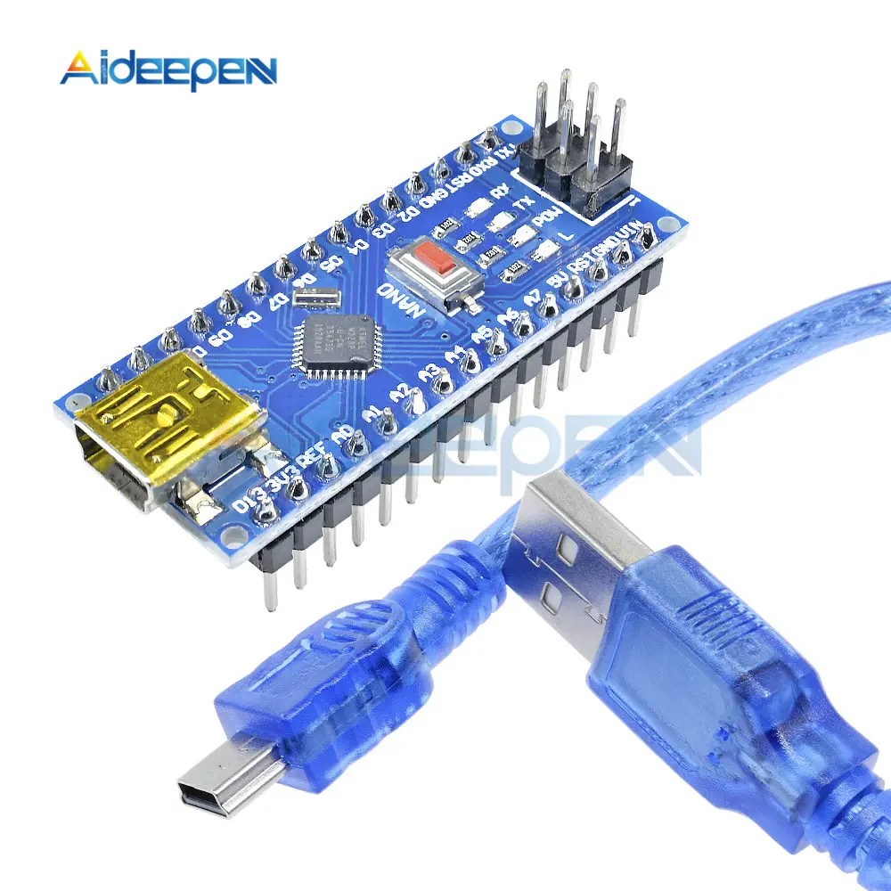
Always attach the dipole antenna to the SMA connector BEFORE powering up the LoRa module otherwise you may damage the HopeRF RFM95 LoRa transceiver module.MISO = Master In Slave Out (data output from slave) MOSI = Master Out Slave In (data output from master) Make the following jumper wire connections between the HopeRF RFM95 LoRa transceiver module and the Arduino Pro Mini. The HopeRF RFM95 LoRa transceiver module.Jumper wires 20 cm long (19x male-male).To connect the FTDI adapter to the Arduino Pro Mini.Ĭonnect Arduino Pro Mini and FTDI adapter with the FTDI cable. Jumper wires 15 cm long (6x female-female).This cable transfers the sketch from computer to the FTDI adapter. USB 2.0 cable, USB-A > Mini USB-B (length: 80 cm).In this tutorial I will be using the FTDI FT232RL adapter.
Arduino mini usb adapter 03 serial#
To communicate with the Arduino Pro Mini with your computer via an USB port an USB to TTL serial adapter is needed. The Arduino Pro Mini does not have an USB connector. Modify ESP8266 module adapter plate for HopeRF RFM95 LoRa transceiver module with RP SMA female edge mount connector With the male pin headers soldered, bottom view. I am not using the Arduino Pro Mini ATmega328P / 5V / 16 MHz because the HopeRF RFM95 LoRa transceiver module uses 3.3V. The Arduino Pro Mini: ATmega168 will not work because there is not enough space.


 0 kommentar(er)
